Friday 19 September 2014

A test PCB

Before I launch off into designing a fully-fledged shield I decided to do a trial. This was mainly to test my ability to design footprints for a number of components and to test their interaction with the Arduino. My aim was to get the MIDI-in and the rotary encoder connections off the breadboard and onto a PCB. I also wanted to try out a 5V voltage regulator and a rail splitter.  All the new footprints and library symbols for KiCad are available on github and here's a PDF of the schematic as shown in this image:


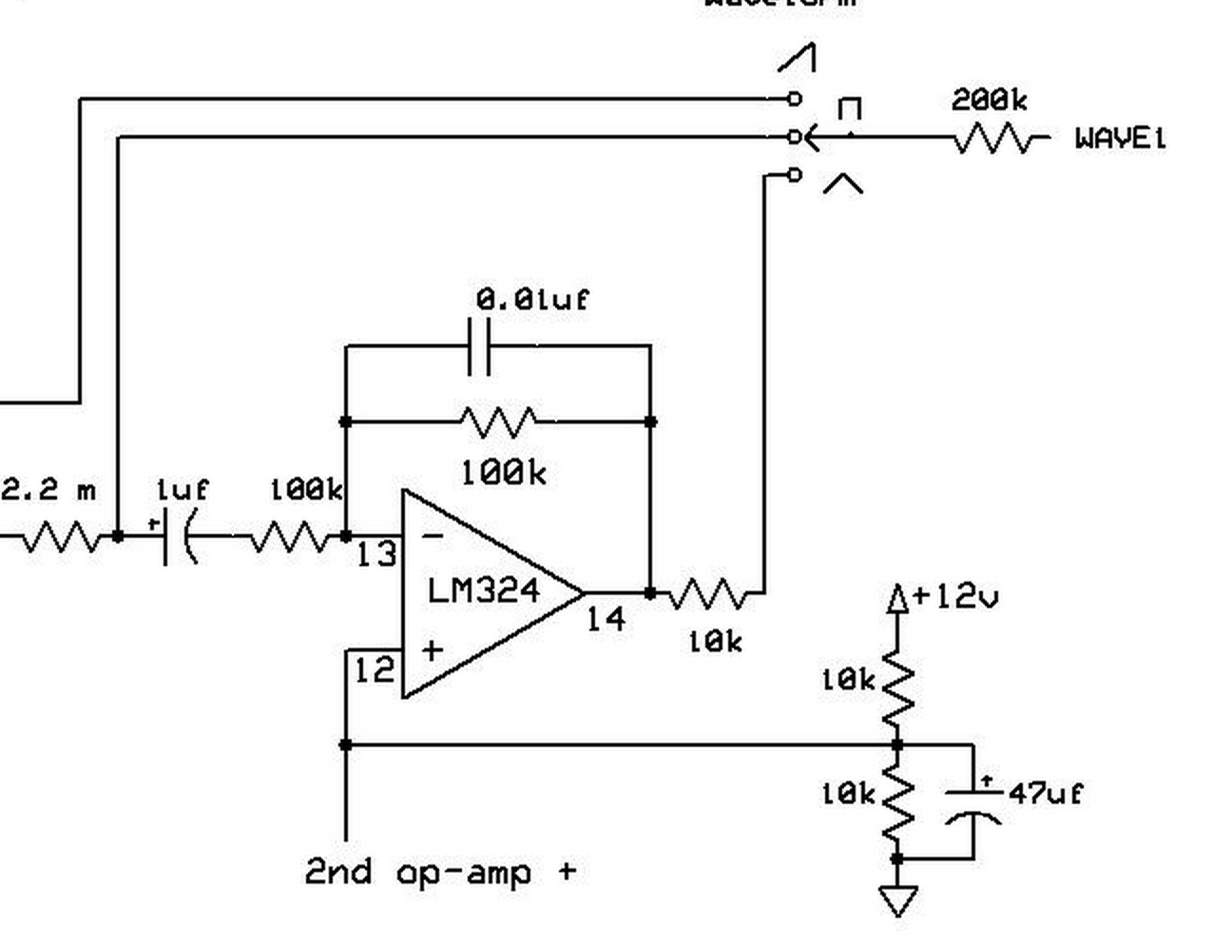
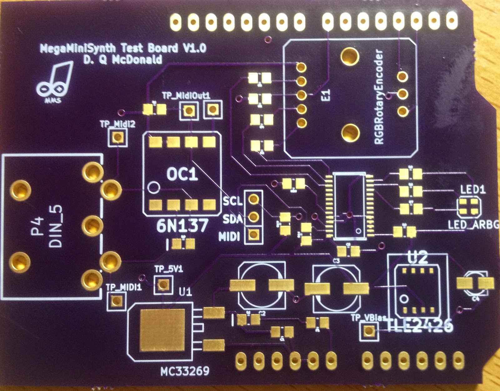
In my original schematic I neglected a resistor in the MIDI in (R13), that's shown in the updated schematics attached. Fortunately the 5PIN DIN socket is pretty chunky and it was easy enough to clip off one of the leads and attach a 200 Ohm resistor. Kind of a hack but part of the reason I did this "throwaway" prototype was to sort out things like this.

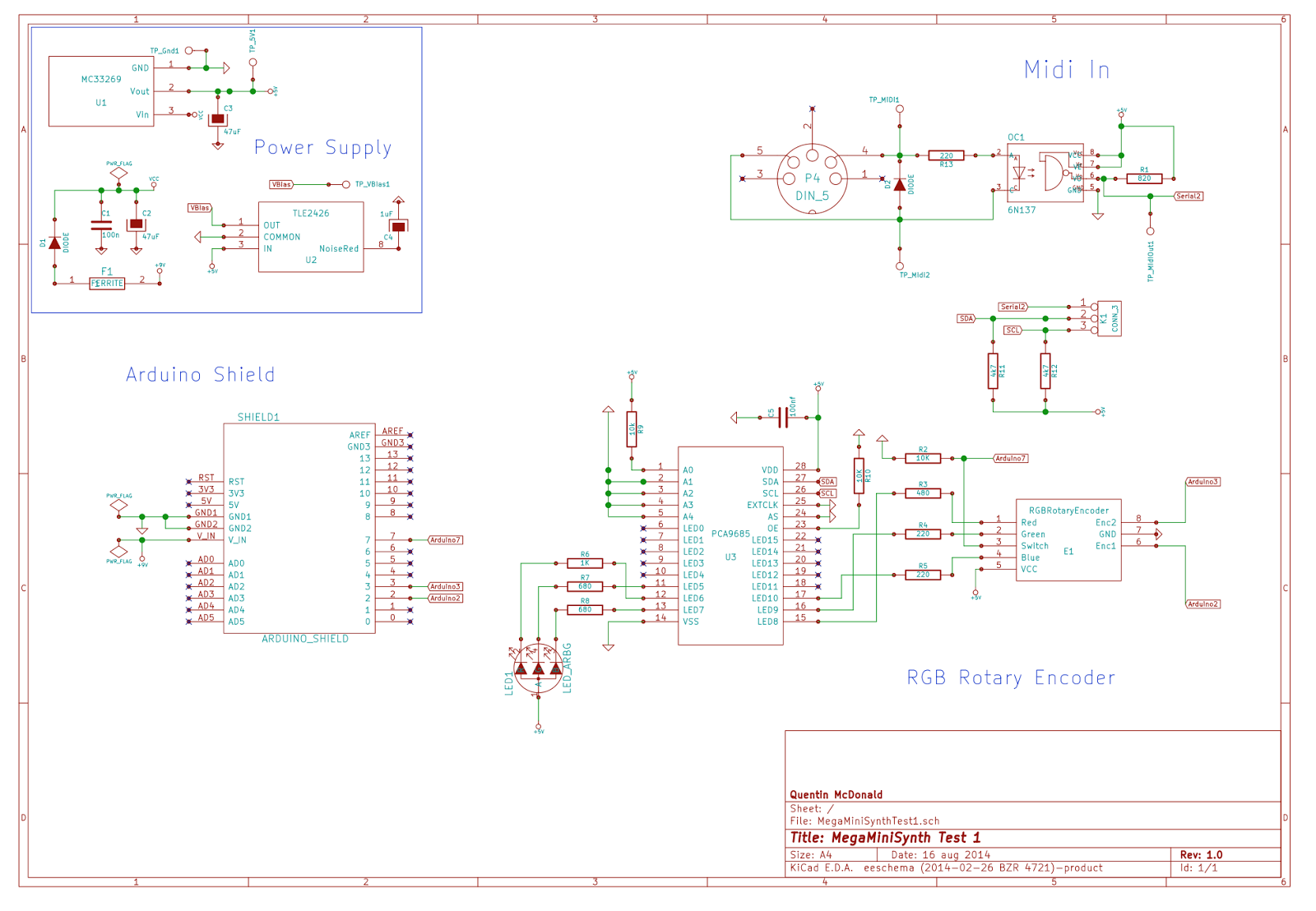
The board layout was pretty straight-forward, I did a regular sized (rather than Mega sized) arduino shield in order to save some money and just use wire jumpers from the MIDI to serial 1 and the SDA/SCK connections.


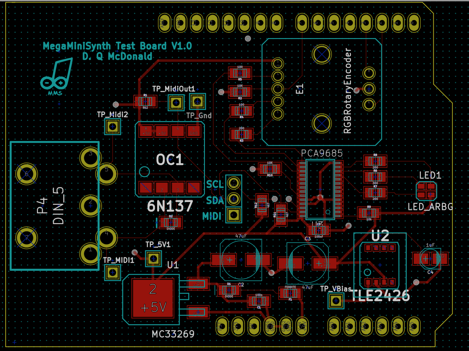
Soldering was pretty straight-forward - the most challenging part was the PCA9685 PWM driver in a 28 pin TSSOP package. It took a bit of flux and braid to remove all the bridges but I'm reasonably confident it's soldered correctly. I could test that the connections seem to make sense, even though my multimeter probes are just fine enough to fit on the 0.5mm pitch pins.  Everything else was fairly easy in comparison, even the RGB LED which more of less sits on the pad, and I was especially pleased with how well the footprint for the rotary encoder worked out since I'd had to develop that from the (less than straight-forward) measurements in the datasheet. When I got the board the encoder clipped in easily and felt quite secure.

Before I sent the board off to OSH Park for manufacture I printed out an actual version and mounted on some foamcore. Then I stuck most of the components on with BlueTak to ensure things would fit:


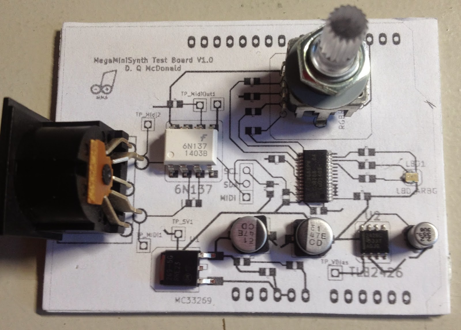
This didn't allow me to catch the missing resistor but at least I had some confidence that the major footprints were nicely sized. When the real board arrived I simply detached these from the prototype and soldered them on. Here's a couple of photos of the final board, with and without components. Note the resistor bridged onto pin4 of the DIN5 socket:


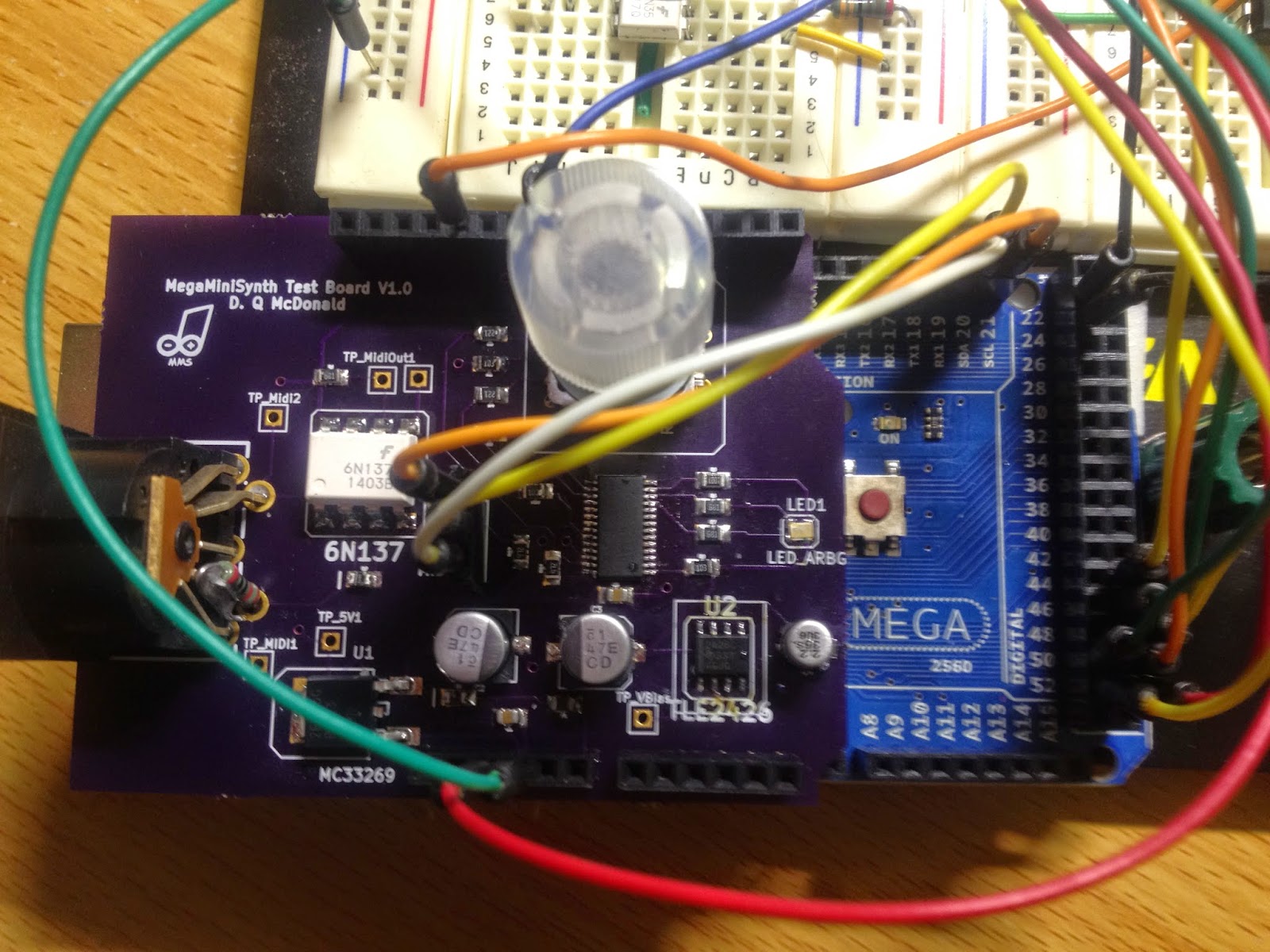
The real test was when the thing was powered up. The absence of magic smoke was a good sign. First test was to measure the voltage coming out of the regulator and the railsplitter. When I remembered I needed to power with 9V (not just USB) things looked good with 4.99V coming out of the regulator and exactly half that out of the railsplitter.

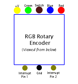
Next test was the rotary encoder - this worked just as I expected both in terms of the pushbutton and the encoder itself. Finally I tried out the MIDI, worked first time and it seems the 6N137 high speed optocoupler works well.

The only thing that wasn't working were the RGB LEDs, those in the encoder and the stand-alone one.  They were on with full brightness for all colors. Perhaps my soldering of that 28 pin IC hadn't been as good as I hoped? Unfortunately tracking this down could be a pain as it could be a hardware, a software (I2C) or even a conceptual problem (maybe you just can't use RGB LEDs this way).  I was all prepared to drag out my oscilloscope and do some I2C logic analysis.

To support this PWM driver I am using the Adafruit library for this IC which was originally designed for this very nice board. I actually bought one of those boards that I hope to use in some (yet to be defined) future project so I feel a little less guilty in using the library here. I turned on some debugging in the library and could see that as long as I set the I2C address for the device correctly (0x41 in my case since I have the A0 pin high and the remaining address pins low) then it could write and then read mode settings correctly from the PCA9685. This was very positive since it showed the chip was working correctly and there was no issue with powering of basic I2C connections.

The actual issue turned out to be simply in the use of the library. With these common anode RGB LEDs the PCA9685 is sinking rather than sourcing current. Therefore PWM works in the opposite direction to what one expects. A full width pulse actually turns the LED off, not on.  Once I adjusted the code for that both the LEDs functioned fine and I'll definitely use the PCA9685 in my final design for the rotary encoder and a couple of indicator LEDs.

With this proof of concept of the some of the basic functionality complete it's now time to start laying out the "proper" shield, and to get the software into a bit better organized shape.


Friday 29 August 2014

Pins and Routing

The Arduino Mega has a heap of pins. But will it be enough? In order to get some idea I've begun to try and enumerate the assignments of the pins. Here's a screenshot of the color coded spreadsheet:


So far it's looking fine, like there'll be enough to go around and some to spare. The actual spreadsheet is available here.  There's a second sheet that lists the pins in numeric order.

Unfortunately listing the pins is one thing, actually routing them on a PCB to where they need to go may be a totally different matter altogether. I've been tossing up how to to handle this. One way would be to make each module a conventional Arduino shield. I'd need to have an additional bus to transfer the audio and modulation signals. The advantage of this is that the routing and component layout would be fairly easy and it would be a neat stack of boards with a very small footprint. The downside is that it would be fairly expensive as a board the size of an Arduino Mega for each module would be quite large. I could add more than one module per shield but that's starting to work against the modular nature of the design. So in that case I think it would make better sense to have a single shield and have the modules attached to that. Something like:

I'm not sure exactly how the LCD screen and the rotary encoders would be arranged but they, along with the mixer and modulation router, would be on the main shield. This shield would overlap the Arduino Mega a little and have pin attachment points for the various modules. This will allow the module boards to be only constrained by size in one dimension - where they mate with the main shield and each one can be considerable smaller than a shield itself.  However the routing of all the pins becomes a lot more complicated. One thing that might make that easier is to make this one shield a four-layer board. I've never laid out a four layer board but it sounds like KiCad can handle it OK and a four-layer board is only twice the price of a two layer one with OSH/Park. Spending a bit more on this one shield will pay off in allowing the module boards to be smaller. 

At the same time I thought about it and realised it likely makes sense to have three oscillators. This was partly from looking at the pins available, partly because the Mega can sustain three Timers and partly because OSH/Park has a minimum order of three so it costs me no more to have three identical waveshapers than two from that point of view. The block diagram now looks like:


Monday 25 August 2014

I SPI with my little eye

A number of the key pieces of technology I'm planning to use rely on the SPI protocol. Therefore before I committed too much effort to any particular one of them I wanted to ensure that the ones I'm hoping to use would be compatible. The SPI protocol uses a single bus which all devices are connected to for clock and data transfer and each device has a "slave select" pin that is set low when the device should expect to receive data. One complication is that SPI is only a de facto standard and there are variants in protocol that mean some devices may not cooperate on the same bus.

The Arduino Mega has both hardware support for SPI, allowing a very fast data rate, and a fully featured SPI library. The devices I want to use are a TFT LCD screen, this has an SD card reader built-in which is also controlled via SPI. I also wanted to use a number of digital potentiometers in place of conventional pots. The proof of concept stage was to convince myself I knew how to control each of these devices and that they would work well together.

The TFT screen was the first thing I tried out. Like all Adafruit products it's well supported and in this case is driven by their GFX library which is used for a number of different displays. This covers a number of basic graphics operations and once one gets used to the coordinate system (0,0 at top left) then it's pretty straight-forward to use. One thing I found almost right away was that the speed of drawing is relatively slow and it's not possible to use full screen redraw to animate without flicker. This was a problem since I want to be able to show dials of some sort to represent internal settings. There's also apparently no "draw filled arc" type function so it's not possible to draw a pie-type dial. However a linear bar "slider" is easier to do anyway and fairly intuitive. I discovered by some trial and error that it's possible to draw a fairly responsive slider bar by careful redrawing of only the parts that change. The code looks like:

  double frac = (double)val/maxval;
  int width = (int)( frac * (RECT_WIDTH-2));

  if( val >= last_val ) {
    // Bar grows - draw it in black:
    tft.fillRect( RECT_X + 1, RECT_Y+1, width, RECT_HEIGHT-2,0x0 );
  } 
  else {
    // Bar shrinks - draw the exposed background area in white:
    tft.fillRect( RECT_X+width, RECT_Y+1, RECT_WIDTH-width-2, RECT_HEIGHT-2,
    0xFFFF );
  }

  last_val = val;

In this way there's minimal redrawing required and the performance, while not perfectly smooth, is acceptable. I also experimented with text, showing the currently playing MIDI note using code like the following in the noteOn() handler for the MIDI library:

  static char* note_string[] = { 
    "C", "C#", "D", "D#", "E", "F", "F#", "G", "G#", "A", "A#", "B"   };
  int octave = (pitch / 12) - 1;
  int note_index = (pitch % 12);

  tft.fillRect(40, 200, 80, 40, 0xFFFF);
  tft.setTextSize( 4 );
  tft.setTextColor( 0x0);
  tft.setCursor( 40,200);
  tft.print(note_string[note_index]);
  tft.print(octave);


This gives a display of the currently playing note as shown in the video below.

Once the screen was working it was on to test if the SD card worked. The simplest way to test seemed to load an image from the card and display it on the TFT. There's an example supplied by Adafruit that does just this. I created my own "splash screen" image and loaded it from the card, it worked just fine. The image is relatively slow to load but it's fine for this one-off usage. So it seems the SD card reading is working OK, for now I'll assume writing will also be fine.

The final step was to try out some digital pots. My first effort was with the MCP4161 Digital Pot.  There was some suggestion these are Arduino compatible but when I looked more closely at the code it seemed the SPI requirements may not play well with the other two devices as it claims to only work with a non-standard SPI library. Indeed I couldn't seem to send them any data. To be honest I didn't try that hard because I already had an alternative to hand - the Analog Devices AD8402 digital pot. Using this tutorial it was pretty easy to figure out how to use them, and this forum post was a reminder that the RS (and SHDN) pins need to be tied to VDD. In the end it was all pretty easy, I first got it working first with a simple sketch from the tutorial that just changed the resistance, and then integrated into my MegaMiniSynth code and hooked up to the rotary encoder and a "slider" display on the TFT. I'd been using a manual pot to control the PWM for the square wave shaper, a good test was if the digital pot could take its place. Again it worked first time, set up as a voltage divider it worked fine. I had been expecting to have to use the logic encoder feature of my DSO to debug the SPI protocol but fortunately that was not necessary. I'm sure there'll be some problems downstream it will come in handy for.

Here's a rather shaky video that illustrates all these working together. My breadboard is getting pretty full - it's time to start thinking about moving some of this stuff to a PCB!


Monday 18 August 2014

Hand soldering a VSSOP package - a steady hand and a good eye

One of the components I've been keen to try is a SP3T digital switch. This will be used for routing such things as the various waveshapes and the modulation from the LFOs and Envelope Generator. Unfortunately it only comes in a VSSOP package (Texas Instruments calls it a DCU but they are, as far as I can tell, equivalent to VSSOP). This has a 0.5mm pitch (spacing) on the pins. What's more the whole package is very small only 2x3mm. In order to experiment with it I'd created a simple converter board from VSSOP to DIP. I realize that convertors are already available but since I could do it myself and only have it cost $1.75 for three from OSH Park and the available ones had to be sent from the US anyway it seemed like a nice little project.

The board itself was not especially complicated:


Fortunately there was already a VSSOP footprint available in KiCad so that made it a bit easier. Since then I have gained a bit more experience with adding footprints to KiCad and I realize if I'd made my own I probably would have made the pads a little longer so as to make the placement easier.

The boards arrived back from OSH Park last week and they were, as always, quite beautiful with their gold and purple finish:


I broke out my USB microscope and began soldering. Almost immediately I began to realize how difficult this task would be. Not only are the pins very small but the whole package is so light that even the lightest touch would displace it. True the package is actually a bit bigger than, say, an 805 resistor or capacitor but in those cases the pins and pads are quite large.

Most advice on the Internet for soldering this type of SMD package is to first tack down one corner, to use lots of flux and clean up with copper anti-soldering braid. I ended up doing all of those things, but found they are easier said than done. I tinned the pads, cleaned up any bridged pins with braid then placed the IC and holding it down with tweezers very firmly from the top I managed to blob a bit of solder in one corner. The pins looked roughly lined up, not perfect but good enough.  I recently got some 0.31mm diameter solder and that was useful. Then fluxed generously again and dragged some solder across the other side. More flux and then lots of time spent with braid to clean up. I've realized the hardest part is getting the braid in actually the right place. It needs to be right up against the pins and for such a small device that's not easy. Generally a little bit of smoke (the good type) showed when I was actually making contact with the solder. Fortunately testing for bridges was pretty easy, I could simply check each pair of pads on the DPI module with a multimeter. There was one stubborn bridge but I got it in the end by briefly heating the bridge directly with the iron before applying the braid. Once all the bridges were gone I could check continuity with the between the actual IC and the DIP pads and they all seemed fine.

Here are some photos of the final result:


As you can see the soldering tip looks huge! These photos were taken before I cleaned up the board so everything looks filthy, including the soldering iron! There's nothing like a close up view to show how messy things really are.

From the side things look a little better:


It's pretty clear the pins are soldered and lined up reasonably well with the pads.

Finally to give it some scale - here's one with a US dime:


All this took about 90 minutes and I needed several boards to get to a final, good result. However I believe that I'd be faster and more accurate next time, which may well be "for real". It was well worth the practice.

After all that effort it would have been extremely disappointing if it hadn't actually worked. Fortunately there was no problem. I hooked the logic pins up to a couple of Arduino pins (with pull down resistors, not sure if they are absolutely necessary but they seemed like a good investment). It worked perfectly first time. There are four states accessible with the two bits - all off and any one of the three output connected to the common. I used it to switch the output from the three waveshapers I have and it was great to be able to hear the waveform change as I pressed the push button on the rotary encoder.  Although there are several SMT packages I'm planning to use I hope this will be the smallest by far.


Thursday 14 August 2014

Bending it like Beckham

Pitch that is. And not a football one. The MIDI library I'm using makes it easy to respond to MIDI messages of all types with the use of callbacks. It's simply a matter of defining a new function and registering that to handle the message:

MIDI.setHandlePitchBend(handlePitchBend);


// A pitch-bend event has been received:
void handlePitchBend( byte channel, int bend )
{
  // Pass the pitchbend onto the oscillators
  OSC1.setPitchBend(bend);

}


The synth is so simple at this point it's hardly a priority but I couldn't resist trying it out. The question was then - how to bend the pitch? In the past I've worked with a MIDI-CV converter. When dealing with control voltages the bending is easy, since the exponential relationship between CV and pitch is handled by the hardware it's simply a matter of a linear interpolation between to get a voltage offset corresponding to the amount of bend.

In this application however I'm working directly in frequencies, or actually Timer periods but they behave like frequencies. There is a discontinuity in the values for each note since there are optimal pre-scalers for each note range as described here. That makes it a little tricky to interpolate between notes without some complicated code and special cases.

In any case when dealing with frequencies it's not a linear relationship. Each octave doubles in frequency. The MIDI standard suggests pitchbend is implemented as +/- two semitones therefore we need to bend by some ratio of 1/6th of an octave (since an octave contains 12 semitones). The code to do this looks like:

    // Implement pitch bend. The MIDI standard suggests that the pitch bend is +/- two 
    // semitones (or two MIDI notes). 
    // To figure out the bend factor we need to find out what multiplication factor
    // we need. This will be. Each octave doubles in frequency and there are tweleve
    // semi-tones per octave. Therefore we need a factor of
    // 2**(r*2/12) or 2**(r/6) where r is the ratio 
    ratio = fabs((float)m_pitch_bend/ MIDI_PITCHBEND_MAX);
    factor = pow(2,(ratio/6));
    if( m_pitch_bend < 0 ){
      freq = musical_freqs[m_note] * factor;
    } else {
      freq = musical_freqs[m_note] / factor;
    }
    OCR1A = freq;


Where m_pitch_bend is the value received from the MIDI library and MIDI_PITCHBEND_MAX is the largest absolute value we'll ever receive (also defined by the library). Once we know how far to bend than calculating a multiplicative factor is quite straight-forward and avoids the issue with discontinuities in the note data. This strategy may well come in useful when it comes to implementing other pitch manipulations in software such as vibrato.

But does this exponential scaling actually make a difference relative to simply scaling linearly? I did some experiments to see if that's the case. Here's scaling from Middle C to D with 50 linear steps:


And here's doing it with 50 exponential steps:


Tell the difference? I can't, but then I don't have a very advanced musical ear. In any case the exponential scaling is easier to implement and seems to work well.


Sunday 10 August 2014

Triangle and Gate

Having demonstrated the ramp and square waves were working well, the latter with PWM I went on to make the triangle waveshaper. This is shown in this section of the PicSynth Schematic:


This involves feeding the non-inverting input with 1/2 VCC. In my case since I'm still running of 5V from the Arduino it's 2.5V.  When I first tried it I was at my initial note - A (440HZ). I got a reasonable looking triangle:


However I found as I lowered the pitch it looked less like a triangle a more like a sort of rounded off square wave:


Interesting enough it still sounds reasonably different to the square wave, quite a bit smoother with less buzz. I experimented with some different values for the integration capacitor and decided that 4.7nF seemed to give a better overall frequency response - still giving an OK triangle at lower frequencies and not attenuating the higher frequencies too much. 

At the same time I did some experiments with a basic gate. Eventually I'll be able to gate the envelope generator but for testing purposes it would be useful to turn the sound on and off in response to notes rather than simply adjusting the pitch of a constantly running oscillator. I experimented with trying to turn the timers off between notes but this caused annoying effects at the start of each note.  Finally I just simply added an NPN transistor with the base attached to an Arduino pin via a 1k resistor to the ground connection of the output that leads to the amp. This is a bit noisy when the gate is off but it's kind of enough to give the idea of what "real" notes would sound like.


Wednesday 6 August 2014

Rotary Encoder

I've been experimenting with the RGB Illuminated Rotary Encoder that I hope to use. It took me a while to figure out the pins, they aren't in the datasheet but in a subsidiary dimensional drawing which shows it as it would appear on a PCB. I did this little diagram to help me solder it up:


I still managed to get the wrong color wire so it took me a while to figure out why the colors were wrong. Luckily that's easily fixed in software with pin assignments. 

Since I last used a Rotary Encoder with Arduino there's been some development and a couple of new libraries.  I've been using the Encoder library. This works best with external interrupt pins so I used 2 and 3 on the Mega. It seems pretty rock solid, in the past I've always had problems missing events - especially with code that polls. With these encoders I can usually generate reliable increments and decrements by a single count for each detent position and they seem to work for slow or rapid twisting. They actually feel pretty nice with a slight click as they rotate.

The illumination part I just did via standard PWM pins on the Mega (4,5,6) and 7 for the switch. The switch is "normally low" and so benefits from a pull-down resistor between pin 7 and ground. In my code I subclassed the Encoder object to make my own class that also knows about the switch and the RGB LED. Here's the definition of the class:

// This class subclasses the Encoder library described here:
// http://www.pjrc.com/teensy/td_libs_Encoder.html
// As such the pins the encoder pins should be attached to hardware interrupts.
// Additions to this class are support for the RGB led and the push button.
// The LED pins should support PWM
// The Button Pin needs a pull-down resistor on it and is normally low.
class RGBEncoder : 
public Encoder {

public:

  RGBEncoder( int enc_pin_1, int enc_pin_2, int red_pin, int blue_pin, int green_pin, int button_pin );

  void begin(); // Start the rotary encoder operating

  void setColor( int red, int green, int blue );
  // Set the color based on the RGB values. 
  // Each one is in the range 0-255;

  void update ( );  // Read the current encoder value, looking for changes

  int getValue( );   // Get the current encoder value

  boolean buttonPressed(); // Returns true if the button has been pressed.


private:

  int m_red_pin;
  int m_green_pin;
  int m_blue_pin;
  int m_button_pin;
  boolean m_button_pressed;
  long int m_button_down_time;
  long int m_button_check_time;

};


The full code is available on github. Currently the push-button detection is pretty simplistic. It uses a short delay period to debounce and simply keeps a flag for when the button has been pressed for more than 10ms. There's a lot more sophisticated treatment of buttons in another rotary encoder library that I'm very tempted to ..... ummm... "borrow".  It would be useful to be able to detect double clicks and to know when the button is being held down while turning. My main human interface will be only two encoders and a small screen so I'll need as much flexibility as I can get.

Ultimately it's not likely I'll want to use the six PWM pins just to drive the RGB LEDs in the two encoders I'll be using. The PWM pins rely on the timers and it's likely I will find better use for them as oscillators or modulators.  Instead I will investigate the use of an LED PWM driver such as the PCA9685 as featured in this Adafruit board. It's I2C driven so can be used with just two pins instead of six. The driver has 16 channels so maybe I'll add a couple of extra RGB LEDs simply for gratuitous effect.

Currently I don't have a lot of useful things I can do with the encoder other than admire the colors and verify it works. I did hook it up to traverse the MIDI notes and to change color - red for higher notes and blue for lower ones. Here's a video: